Alignment Lift Levelness: What Buyers Should Verify Before Acceptance
For H4 four-post and BH6108 recessed alignment lifts, specify working positions, support-surface checks and acceptance records separately from aligner calibration.
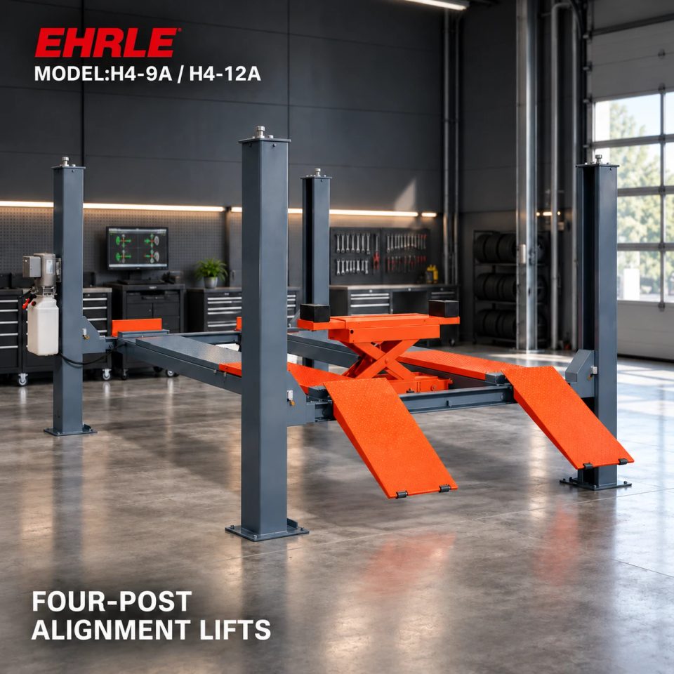
Define alignment-bay acceptance before ordering
An alignment lift needs more than the right capacity and runway dimensions. Buyers should agree how the installed wheel-support surfaces will be checked at the intended alignment position, which requirements govern that check and how the measuring system will be commissioned. Those are separate questions from whether the lift fits the building.
This guide uses the H4-9A/H4-12A four-post range and the BH6108 recessed scissor lift to define the acceptance documents to request. It does not prescribe a level tolerance, an adjustment procedure or a calibration setting.
H4: identify the exact runway and working-position requirements
H4-9A lists 4,000 kg capacity with 4,600 × 500 mm runways; H4-12A lists 6,000 kg with 5,700 × 650 mm runways. Runway lengths exclude ramps. Both list 1,800 mm lifting height, mechanical locking and single-point manual release.
These values describe equipment selection, not a numerical runway-level guarantee. Ask for the exact model’s installed-level requirements and the permitted alignment working positions, including the prescribed load-holding condition. Maximum lifting height alone does not establish that every stopping position is an approved alignment position.
BH6108: pit construction and alignment acceptance are distinct
BH6108 lists a 4,000 kg main lift with 4,500 × 630 mm runways, plus an integrated 3,000 kg secondary scissor lift. Its installation uses two prepared pits and requires the final factory foundation drawing.
A pit built to the correct outline is not, by itself, a recorded check of the installed wheel-support surfaces. Ask how the final runway installation and intended alignment position will be verified after installation. Keep secondary-lift capacity and operation separate from wheel-supported alignment acceptance; the secondary stage’s rating supplies no runway-level specification.
Measure the surfaces that actually support the wheels
For the proposed vehicle range, identify the relevant wheel-support locations on both runways, including the selected turnplates and rear slip plates. Ask the lift supplier and alignment-equipment provider which reference points, working condition and measuring method their documents require.
The current product records publish no universal cross-runway, longitudinal or diagonal level tolerance. They also do not establish an unloaded measurement as proof of every loaded condition. Have the responsible providers specify the test condition and applicable acceptance criteria rather than judging levelness from a photograph, a concrete surface or a single convenient point on the structure.
A measuring-system procedure does not replace the lift documents
Hunter’s WinAlign Operation Instructions, Basic Operation Information, pages 46 and 49, describe a level rack condition in the relevant compensation procedures, including the use of leveling legs where present. This demonstrates that the equipment’s support condition belongs in the alignment workflow.
It does not establish that an EHRLE H4 or BH6108 has the same leveling arrangement. Follow the instructions for the actual lift and aligner combination. Keep mechanical installation acceptance, the aligner’s calibration or reference setup, and a vehicle’s measurement/compensation procedure separately identified. A completed software procedure alone is not evidence that the lift meets its installation requirements.
Agree who resolves a mismatch between the two systems
Before ordering, ask the lift supplier and alignment-equipment provider to review the same layout, working height and plate package. Request any model-specific requirements that affect the installed reference surfaces or measuring-system setup. If their requirements are unclear or appear inconsistent, resolve them before acceptance.
Neither current EHRLE record supplies an alignment-accuracy guarantee, calibration interval or universal compatibility list. Do not borrow another brand’s leveling mechanism, adjustment values or software correction limits. Structural, anchor, pit and electrical requirements must remain tied to the ordered model documents and qualified site assessment.
A practical acceptance schedule for the quotation
Specify:
1. Exact lift model and supplied runway, turnplate and slip-plate configuration.
2. Intended vehicle range and alignment working positions.
3. Applicable lift and aligner documents and their revisions.
4. Reference surfaces and measurement points to be checked.
5. Required load/support condition and model-specific tolerances.
6. Qualified installer and alignment-provider responsibilities.
7. Recorded results, unresolved items and the documented acceptance decision.
Ask what changes require rechecking, such as an altered plate package, a moved installation or relevant service work; the applicable providers must define the scope and schedule. Send EHRLE your alignment-system details and intended H4 or BH6108 layout to clarify this acceptance pack with the quotation.
FAQ: Does an H4 1,800 mm lifting height prove alignment readiness there?
No. It is the listed lifting-height figure. Obtain the approved alignment working-position and support-condition requirements, then have the installed equipment checked against the applicable criteria.
FAQ: Can correct BH6108 pit dimensions replace a runway-level report?
No. Civil-work dimensions and the final installed support-surface condition answer different questions. Request both the final construction drawing and the appropriate installation/acceptance records.
FAQ: What millimetre tolerance should I apply to both models?
The current records establish no shared numerical tolerance. Obtain the exact lift and aligner requirements for the proposed configuration; this article does not substitute a guessed value.
Sources and image notes
EHRLE H4-9A/H4-12A and BH6108 published, enabled and verified records were checked on 27 October 2026; related pages are linked below. General workflow reference: Hunter WinAlign Operation Instructions, document 3850-T, Basic Operation Information pages 46 and 49, available at hunter.com. No Hunter leveling mechanism, tolerance or operating sequence is transferred to EHRLE equipment.
Cover and gallery are product scene illustrations, not surveyed installations or level measurements. Illustrated alignment accessories do not prove inclusion. This guide adds working-position, reference-surface and acceptance-record detail beyond earlier runway sizing and turnplate-interface articles.
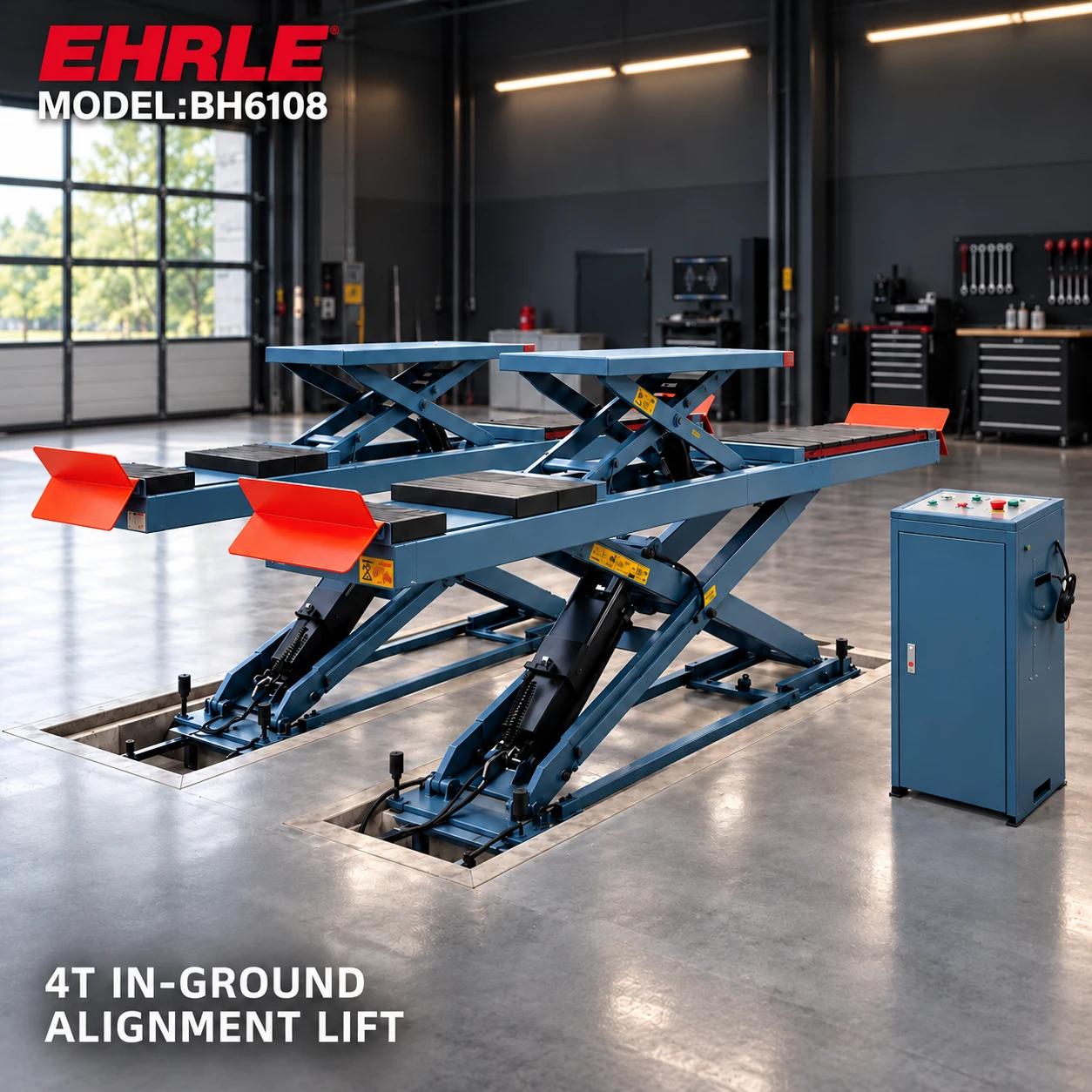
Product scene illustration. Final factory construction documents and installed alignment-position checks serve different purposes; the image proves neither.