Four-Post Lift Bay Planning: Runway Length, Overall Size and Vehicle Clearance
Plan a four-post lift bay using the right measurements. Compare H4 alignment-lift dimensions and BH88 parking requirements before preparing a site layout.
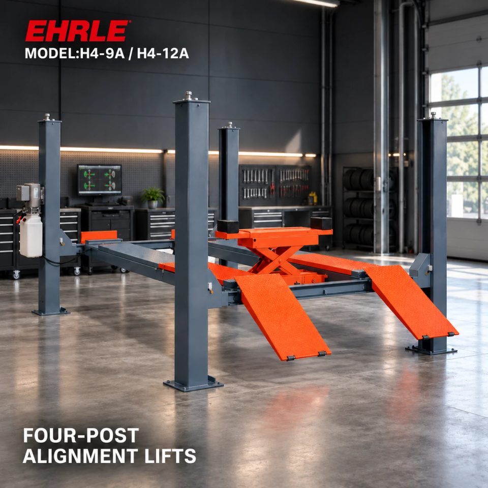
Start with the job: alignment or parking
Four posts describe the support arrangement, not a complete statement of intended use. The EHRLE H4-9A and H4-12A product information describes four-post alignment lifts. The BH88 is documented for two-level parking and storage. A parking lift should not be selected as an alignment lift simply because both designs have four posts.
First state what the bay must do. For alignment work, specify the measuring equipment and the required runway accessories. For parking, provide details of the intended upper and lower vehicles and the available building space. Then compare the dimensions for the relevant model.
Keep runway length and total equipment length separate
The H4-9A lists 4,600 mm runway length excluding ramps, but 5,300 mm total length. The H4-12A lists 5,700 mm runway length excluding ramps and 6,500 mm total length. Drawing a bay around runway length alone leaves out part of the stated equipment envelope.
Use the full installation drawing for floor planning. Even the total equipment length is not a complete working-bay recommendation: vehicle approach, maneuvering and access require space beyond the equipment. The 700 mm and 800 mm differences between listed total and runway lengths should not be treated as separately specified ramp lengths; confirm the actual components and measurement endpoints on the drawing.
Three width measurements answer different questions
For the H4-9A, the listed runway width is 500 mm, width between columns is 2,743 mm and total equipment width is 3,160 mm. For the H4-12A, those values are 650 mm, 3,050 mm and 3,467 mm respectively. The listed inner runway spacing is 1,000 mm.
Runway width concerns the tire-support surface, column spacing concerns an opening between structural members, and total width concerns the equipment envelope. None independently establishes a universal vehicle fit. Ask the supplier to check tire placement, body clearance and the intended vehicle approach against the selected configuration. Do not substitute one width for another in the workshop plan.
A larger H4 model changes the floor plan as well as the rating
The H4-9A is rated at 4,000 kg and the H4-12A at 6,000 kg. Moving to the H4-12A adds 1,200 mm to listed total length and 307 mm to total width. Both models list 1,800 mm lifting height and 1,950 mm post height.
These figures are useful for an initial shortlist, but they do not establish an approved wheelbase range or a ceiling-height requirement. Request the usable tire positions and the actual raised-vehicle envelope. If the intended vehicle requires the higher rating, confirm that the larger layout also fits the site rather than treating capacity as the only decision.
For BH88 parking, review both vehicles and the building
The BH88 lists a 2,700 kg lifting capacity, 4,700 mm platform length, 1,950 mm platform outer width and overall dimensions of 5,400 × 2,700 × 2,100 mm. Its 1,950 mm platform outer width is not the overall equipment width, and it is not a substitute for a tire-placement or body-clearance check.
The record lists a minimum site height of 3,600 mm and clear lifting height of 2,000 mm. Those figures do not guarantee that any pair of cars will fit. Review both vehicle heights and the platform movement envelope with the final parking layout. The published information specifically requires vehicle-dependent upper and lower clearance checks.
Complete the layout with the supplied scope and power configuration
The H4 rolling jack is optional. Its capacity, adapters, lifting range and quantity require separate confirmation; the complete lift rating does not establish the jack rating. Alignment measuring equipment and accessories are separate unless expressly included, and supplied turntables should be specified. A pictured accessory is not proof of standard inclusion.
The listed electrical options also differ: H4-9A offers 220/380 V three-phase, while H4-12A lists 110/220 V single-phase, both with 50/60 Hz options. BH88 lists 220 V or 380 V input; confirm its phase and frequency for the order. These are configuration choices, not a universal supply accepted by one machine.
Send a usable site brief before requesting a quotation
Include these items in the enquiry:
1. Intended use: alignment work or parking/storage.
2. Exact vehicle models, weights and dimensions; for parking, identify both vehicles.
3. A measured floor plan with entrances, fixed obstructions and available height.
4. Required access around the lift and the intended vehicle approach.
5. Alignment equipment and accessories, or parking-layout requirements, as applicable.
6. Voltage, phase, frequency and delivery destination.
Request a model-specific drawing with measurement endpoints, the supplied equipment list and the installation and operating documents. Have the appropriate professional assess the actual site against those documents. This planning comparison does not prescribe foundation thickness, anchors or operating clearances.
FAQ: Can I use the H4 runway length as the required bay length?
No. The listed runway lengths exclude ramps, and total equipment lengths are longer. Approach and working space must also be considered beyond the equipment dimensions.
FAQ: Is a BH88 suitable for alignment work because it has four posts?
The current BH88 record documents parking and storage. For a four-post alignment bay, review H4-9A or H4-12A and confirm the required measuring equipment and accessories.
FAQ: Does the stated BH88 minimum site height guarantee room for two cars?
No. The listed 3,600 mm minimum is a starting requirement, not approval for every vehicle pair. Confirm upper and lower clearances and the movement envelope for the intended cars.
Specification and image notes
The dimensions and configuration distinctions above come from the EHRLE H4-9A/H4-12A and BH88 product records checked on 8 October 2026. Related product pages are linked below. Cover and gallery images are product scene illustrations, not customer installation evidence, scaled planning drawings or proof of included accessories. Confirm the supplied model, layout and documentation in the quotation.
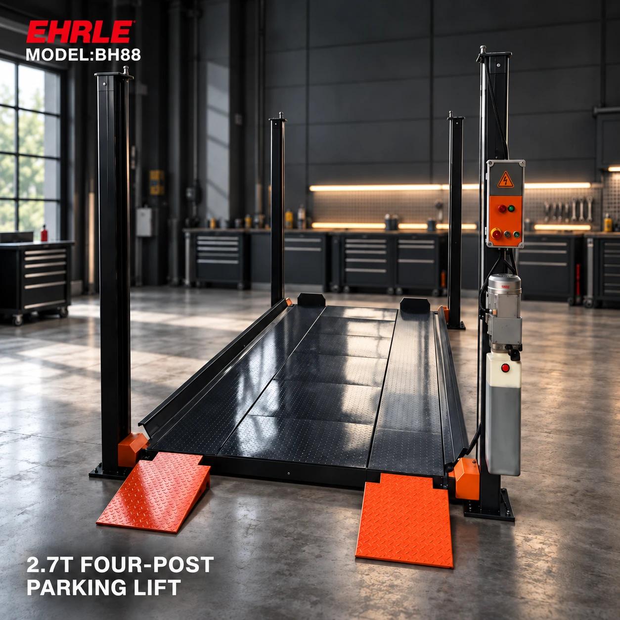
Product scene illustration. Check the full equipment envelope and vehicle-specific upper and lower clearances against the final drawing.