One Portable Lift, Two Bays? Plan the Move Before You Buy
Sharing a portable lift between bays means repositioning unloaded equipment under its instructions, not transporting a supported vehicle. Use these 6010B/C and BH-34T examples to plan the route, mobility components and storage before ordering.
Key takeaways
• 6010B/C repositioning is limited to an unloaded, fully lowered lift using the specified mobility arrangement.
• BH-34T transport wheels and trolley handle move unloaded columns, not a supported vehicle.
• Review the movement route, storage position and lifting positions as three separate parts of the layout.
• Mobility-kit scope, movement dimensions and utility arrangements belong in the purchase brief.
1. Decide whether you need a movable lift or a vehicle transporter
These EHRLE models support moving the equipment between suitable positions. Their published records do not authorize transporting a vehicle on the lift. That distinction should be settled before a workshop buys equipment to share between bays.
Consider a hypothetical shop that wants one 6010 lift for two service areas. A workable proposal moves the unloaded equipment between assessed positions under its instructions; it does not move a raised car from one area to the other. If moving the vehicle while supported is the actual requirement, the proposed workflow needs different, expressly approved equipment.
2. Specify the 6010B/C mobility kit as part of the order
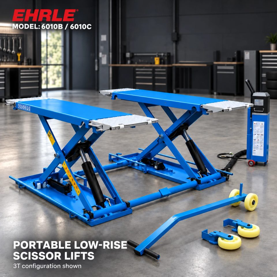
The 6010B and 6010C records describe a removable mobility kit and require the supplied accessory scope to be agreed. Both must be unloaded and fully lowered before repositioning. “Portable” on the product title is therefore not a complete list of the moving components included in the quotation.
Their service dimensions also differ: 6010B lists 3,000 kg capacity and platforms 1,420 mm long, extending to 2,028 mm, with 460 mm width each. 6010C lists 4,000 kg and 1,570–2,175 mm lengths with 530 mm width each. These are platform dimensions, not the overall movement envelope.
For the chosen model, establish the complete width, length and clearance needed in its manufacturer-prescribed movement configuration, including the handling components. Do not calculate doorway fit from one platform’s width or copy the smaller model’s dimensions.
3. Plan BH-34T column movement separately from the lifting set
BH-34T has integrated transport wheels and a trolley handle for unloaded-column repositioning. Its standard set consists of four columns, each rated at 8,500 kg, with 34,000 kg combined capacity. The listed column weight is 760 kg.
The 760 kg figure is equipment mass, not a statement of the effort needed to push or pull it. It supplies no approved crew size, slope limit or manual-handling method. Get the actual transport arrangement and route conditions assessed using the supplied instructions.
Moving a column into a bay is also separate from assembling the approved vehicle-support configuration. Six- and eight-column arrangements are order options requiring their own vehicle and control approval. A storage row of columns is not, by itself, an identified operating set.
4. Draw the route and the storage position, not just the service bay
Show where equipment is stored, how it reaches each intended position and where it is used. Record doorway openings, turns, thresholds and other route features for review. A straight doorway measurement alone does not establish that the complete equipment can make a turn beyond it.
Ask for the allowed surface and movement conditions for the actual supplied transport arrangement. Neither current record supplies a universal allowable ramp gradient, threshold height or turning radius. Those limits cannot be derived from the lifting-capacity rating.
Plan storage with access to the equipment and its accessories. Do not assume that a portable scissor lift may be stood upright, stacked or stored outdoors: the records used here establish none of those storage permissions.
5. Recheck the destination position and its utilities
A route that permits unloaded movement does not establish a suitable lifting location. For BH-34T, the product record requires appropriate floor levelness and bearing capacity for the concentrated column loads. For 6010B/C, the vehicle support, floor and operating arrangement must match the supplied instructions at the destination.
Utility planning differs too. 6010B/C uses an electro-hydraulic drive, with electric release standard and a pneumatic-release option. BH-34T lists rechargeable 24 V operation and AC 220 V charging. Those descriptions do not mean both locations need the same connections.
Identify how services and accessories will be managed under the prescribed relocation procedure. Do not assume a hose, cable or connection can simply be dragged, extended or disconnected in any equipment condition.
6. Put a two-location review into the buying brief
Before ordering, provide:
1. Exact model and the equipment-sharing task.
2. Storage area, measured movement route and each intended operating position.
3. Supplied mobility components and their identification.
4. The full movement envelope and permitted route/storage conditions.
5. Utility arrangements, accessories and the manufacturer’s relocation instructions.
6. Qualified site review and operator training for the actual arrangement.
Where practical, agree a manufacturer-defined unloaded handover demonstration of the intended relocation arrangement. Resolve missing route or component information before treating the lift as usable in both positions.
Contact EHRLE with your two-bay layout to assess the 6010B/C mobility package or a BH-34T fleet-bay arrangement. Their capacities and supported vehicle types are different; the comparison concerns mobility evidence, not interchangeable service capability.
Frequently asked questions
Can a 6010B or 6010C move with a car on it?
No. The published arrangement requires the lift to be unloaded and fully lowered before repositioning with its mobility kit.
Do BH-34T transport wheels authorize moving the raised bus?
No. They are documented for moving unloaded columns. Do not move loaded columns.
Does 530 mm platform width mean 6010C fits through a 530 mm opening?
No. That value is the width of each platform, not the overall equipment/handling envelope. Obtain the actual movement dimensions.
Can a lift-approved floor automatically be used as any relocation route?
The movement conditions and operating-position conditions need their own review. A lifting-position assessment does not establish permission for every route feature or storage arrangement.
Sources and image notes
This guide uses published, enabled and verified EHRLE 6010B/6010C and BH-34T product records checked on 28 October 2026. Related pages are linked below. The two-bay example is hypothetical, not a customer installation or a claim of demonstrated relocation time. No movement procedure or numerical route limit from another manufacturer is applied here.
Cover and gallery are product scene illustrations. The 6010B/C cover shows a 3T configuration; it does not establish the 4T model’s movement envelope. The BH-34T bus scene is not a demonstration of moving loaded columns. This article adds mobility-component scope, movement geometry and storage planning beyond the earlier operating-floor assessment.
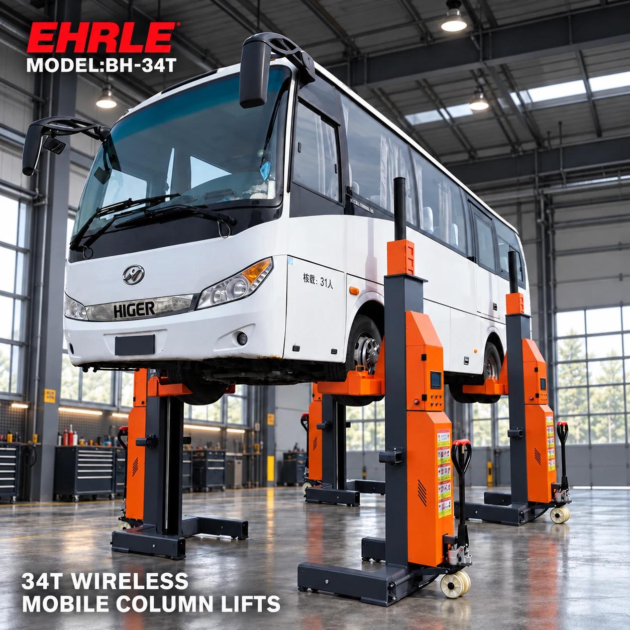
Product scene illustration. Review the unloaded transport arrangement separately from the approved lifting configuration and operating floor.