Alignment Lift Runway Width and Spacing: Will Your Vehicle’s Tires Fit?
Compare H4-9A, H4-12A and BH6108 runway dimensions, then request a vehicle-specific review of tire positions, usable support surfaces and alignment placement.
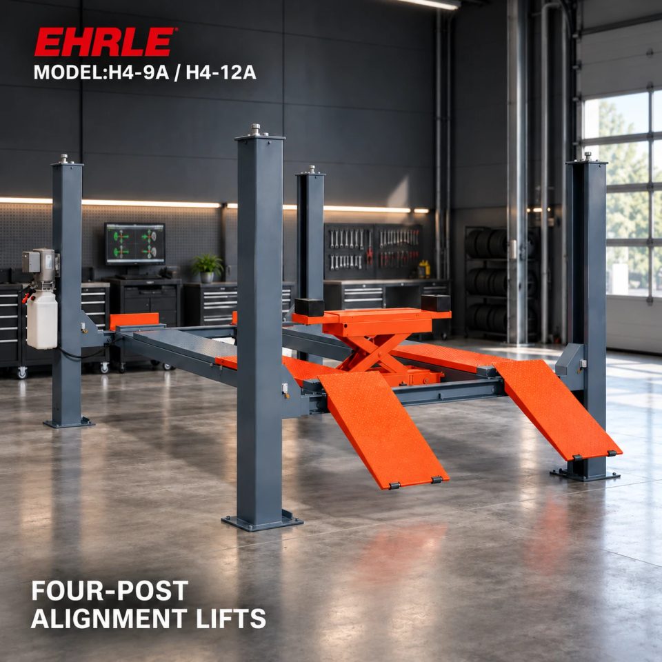
Match the vehicle to the tire-supporting surfaces
A drive-on alignment lift supports the vehicle through its tires on two runways. Before choosing the model, ask the supplier to confirm where the intended vehicles’ tires will sit on the supplied arrangement. Rated capacity, equipment width and runway width answer different questions.
This guide compares the published H4-9A, H4-12A and BH6108 runway dimensions as inputs to that assessment. It does not provide a universal permitted wheel-track range or a rule for how close a tire may sit to a runway edge. Those limits need the exact equipment documents and a vehicle-specific review.
H4-9A and H4-12A: label each width before comparing
The H4-9A lists 500 mm runway width, 2,743 mm width between columns and 3,160 mm total width. The H4-12A lists 650 mm runway width, 3,050 mm between columns and 3,467 mm total width. Both share a listed 1,000 mm inner runway spacing for the documented configuration.
Use the runway dimensions when asking about tire support, the column opening when reviewing passage between the structures, and overall width when planning the equipment envelope. Do not replace a missing tire-fit assessment with the much larger total-width figure. Ask the supplier’s drawing to label the actual edges and measuring points.
Why a wider runway does not establish every vehicle’s fit
H4-12A has a wider listed runway and a higher main rating than H4-9A: 650 mm and 6,000 kg versus 500 mm and 4,000 kg. That supports an initial comparison, but it does not establish that every vehicle below six tonnes fits the H4-12A.
The vehicle’s front and rear tire positions, tire widths and permitted placement must be reviewed together with the runway arrangement. Ask for the actual usable support area and any positioning restrictions. A tire-width value alone does not show where both left and right tires will sit; a vehicle’s overall body width does not describe those tire positions either.
BH6108: do not substitute pit spacing for runway spacing
BH6108 lists 630 mm width per runway and 4,500 mm runway length, with 4,000 kg main capacity. Its specification table does not give an approved vehicle wheel-track range. The reference pit plan is a civil-layout reference, not a vehicle-compatibility specification.
Obtain the final drawing showing the installed runways and their usable support surfaces. Do not use a pit-gap measurement as a tire-position limit or transfer the H4 models’ 1,000 mm inner spacing to BH6108. The fact that BH6108 is recessed does not, by itself, determine the range of vehicle tire positions it accepts.
Check tire positions along the runway as well as across it
H4-9A lists 4,600 mm runway length and H4-12A lists 5,700 mm, both excluding approach ramps. BH6108 lists 4,500 mm runway length. These are equipment dimensions; none is a published maximum vehicle wheelbase for this guide to promise.
For alignment work, ask the supplier to show the intended front-wheel positions, rear-wheel positions and applicable turnplate/slip-plate arrangement for each vehicle. The BH6108 record describes adjustable front turnplate positions and rear slip plates, but does not provide a numerical adjustment range. Obtain that range and the corresponding arrangement rather than inferring it from runway length.
Send a vehicle schedule that supports an actual fit review
Include the following with an enquiry:
1. Vehicle make, model, variant and relevant loaded weight.
2. Front and rear wheel-track information, with its measurement definition, plus tire sizes or measured widths.
3. Wheelbase, relevant body dimensions and any unusual wheel arrangement.
4. The intended alignment system and working positions.
5. The proposed lift model and the dimensioned bay layout.
Request a drawing or written assessment identifying usable runway surfaces, spacing, permitted tire placement and the applicable longitudinal positioning limits. Ask the supplier to flag missing vehicle information and any model that remains unverified. Do not assume dual wheels or another unusual arrangement is accepted without explicit review.
Keep loading access and secondary support as separate approvals
A confirmed runway fit does not establish that the vehicle can negotiate the approach ramps or that an alignment measuring system is compatible. Those conditions still need their own checks. If wheel-free work is required, the support arrangement changes and must also be assessed separately.
The H4 rolling jack is optional, with its rating and accessories to be confirmed. BH6108 instead lists an integrated secondary scissor stage rated at 3,000 kg. Neither auxiliary arrangement inherits the main lift’s rating or becomes suitable merely because the vehicle’s tires fit the runways.
Send EHRLE the vehicle schedule to discuss H4-9A, H4-12A or BH6108. Request confirmation of tire support, alignment positions and the ordered configuration before treating a model as suitable for the intended fleet.
FAQ: Is runway width the same as the vehicle wheel track?
No. Runway width describes one equipment surface. Vehicle wheel-track information describes the lateral wheel arrangement, using a stated measurement definition. The supplier needs both, together with tire dimensions and permitted placement, to assess fit.
FAQ: Can I calculate an approved tire-edge allowance from the published widths?
The current records do not establish a universal tire-edge allowance. Obtain the exact usable support limits and positioning instructions for the selected lift. Do not turn a dimensional calculation into a manufacturer-approved operating limit.
FAQ: Does the H4-12A 6T rating guarantee that a wide van will fit?
No. Check its actual tire arrangement, runway placement, body passage and loading path as well as weight. The current product record explicitly treats capacity, runway length and width as separate selection conditions.
Sources and image notes
This guide uses published, enabled and verified EHRLE H4-9A/H4-12A and BH6108 records checked on 19 October 2026. Related pages are linked below. It fills the lateral tire-placement assessment gap left by earlier guides about bay footprint, approach clearance and wheel-removal support.
The cover and gallery are product scene illustrations, not scaled drawings or customer installations. The combined H4 image does not identify one dimensionally exact H4 version. Neither image establishes approved tire placement, supplied measuring equipment or accessory inclusion. Use the selected model drawing for those decisions.
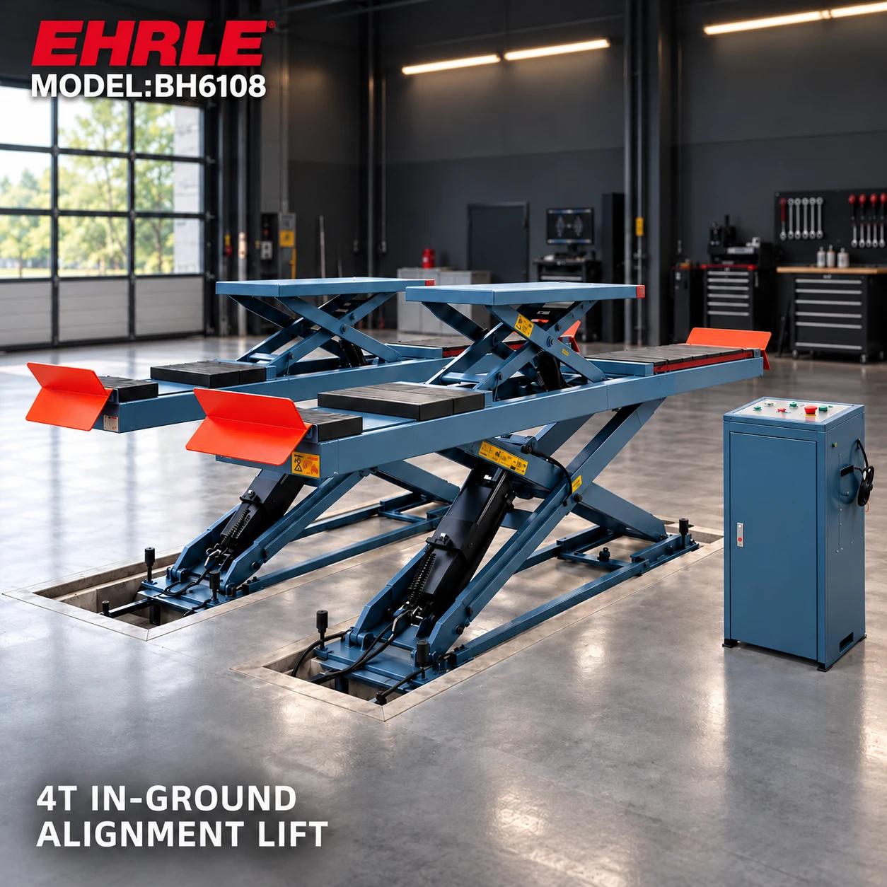
Product scene illustration. The listed width is 630 mm per runway; obtain the exact spacing and permitted vehicle positions from the selected drawing.