Scissor Lift Control Cabinet Placement: Plan Pendant Reach and Service Routes
Plan the complete 6016 or 6105B bay: confirm control-cabinet dimensions, wired-pendant reach, service routes and approved operating positions before installation.
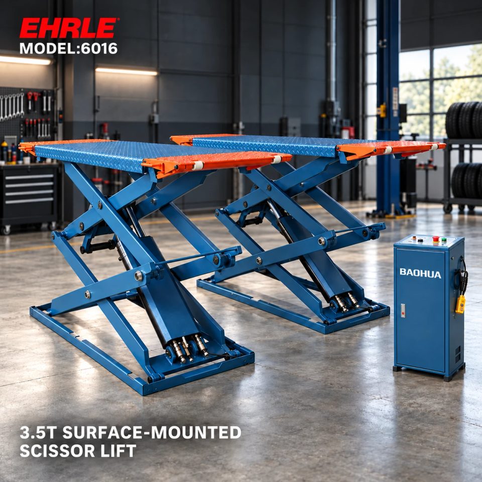
Draw the operating station as well as the lifting platforms
A bay drawing that shows only the lift platforms leaves an important part of the equipment unresolved. Both EHRLE 6016 and 6105B list a separate control cabinet and wired pendant. Their positions, connections and operating access belong in the layout before the installation plan is accepted.
Start by asking the supplier to show the complete supplied arrangement on the measured workshop plan. A cabinet placed beside a lift in a product illustration is not a dimensioned recommendation for the actual bay. This guide identifies procurement and layout questions, not a wiring or operating procedure.
6016: confirm the cabinet envelope and pendant reach
The 6016 is a 3,500 kg surface-mounted full-rise double-scissor lift with hinged platform ends, 24 V controls, a separate cabinet and wired pendant. Its product FAQ explicitly leaves cabinet dimensions and pendant cable length to be obtained with the equipment layout.
Request the cabinet footprint, height, service-access requirements, connection points and supplied pendant cable length. Ask which operating positions the supplier approves for the selected vehicle and lift arrangement. A cable length on its own is not a confirmed usable working radius: its routing and the manufacturer’s instructions also need to be considered. Do not estimate these dimensions from the image.
6105B: resolve the operating station before recess construction
The 6105B is a 3,500 kg recessed double-scissor lift, also listing a separate cabinet, wired pendant and 24 V controls. Its installation documents must address the pits and service routes for the selected version. Standard single-side platform extension and optional double-side extension should be identified in that same configuration.
Ask the final drawing to locate the cabinet, connections and approved service routes relative to the recesses and surrounding floor. Do not finish floor work from a platform-only outline and assume the cabinet can be connected anywhere afterward. The current product record provides no universal cabinet offset, trench depth or hose length for this article to prescribe.
Compare the actual route with the intended vehicle and workshop movement
Show vehicle approach, platform movement, door access, passageways and fixed obstructions on the proposed layout. Ask the supplier and qualified installer to assess whether the operating station and its connections fit that arrangement, including access to the controls and the views required by the operating instructions.
Identify where the pendant will be used and stored, and how its cable and other services will be managed under the approved plan. The objective is to resolve potential interference in the documented layout. Do not infer permission to operate from every location that the pendant can physically reach.
A longer hose or cable is a configuration question
If the preferred cabinet location is beyond the supplied connection arrangement, request a supplier-approved solution before ordering. Ask whether different hose or cable lengths are available, which parts are supplied and which drawing applies. An apparent gap in the plan should remain an unresolved requirement until that confirmation is available.
The current 6016 and 6105B records do not establish interchangeable cabinets, pendants or service kits. Equal capacity and 24 V control descriptions are not proof that their components can be exchanged. Do not splice, extend or relocate equipment based on this article; electrical and hydraulic work must follow the exact equipment instructions and qualified assessment.
Separate 24 V controls from the workshop supply
Both models list 220 V or 380 V supply choices with phase and frequency to be confirmed. Their 24 V control specification is a separate entry. It does not establish a 24 V workshop power input or make the cabinet placement independent of the supplied electrical configuration.
Include the available site supply and its proposed location with the layout enquiry. Request the applicable electrical documentation for the ordered version. Cable sizing, protective devices and connection details must come from the model documents and qualified installer’s site review, not from the control-voltage number.
A compact layout pack for quotation and handover
Provide EHRLE with the vehicle range, selected 6016 or 6105B configuration and a measured plan. Ask the supplier to return:
1. Cabinet dimensions, connection positions and required operating/service access.
2. Supplied pendant cable and service-connection lengths, with any approved options identified.
3. The operating positions and visibility requirements described by the instructions.
4. A coordinated route plan, including the recess interfaces where applicable.
5. An itemized connection/accessory list and the matching installation and operating documents.
Have the supplier and installer resolve missing dimensions before finalizing the equipment location or civil work. At handover, compare the delivered cabinet, pendant and connection package with the approved arrangement. Keep the final layout with the equipment documents so a later relocation is assessed against the actual supplied system.
FAQ: Can the cabinet be located wherever the pendant reaches?
Physical reach alone does not establish an approved operating position. Confirm routing, control access and the manufacturer’s operating-position and visibility requirements for the actual bay.
FAQ: Do 6016 and 6105B have the same cabinet and connection kit?
Their current records both list separate cabinets and wired pendants, but do not establish component identity or interchangeability. Obtain the configuration-specific dimensions and parts list for each quotation.
FAQ: What exact distance should I leave beside the cabinet?
No verified universal clearance is supplied in the current product records. Request the operating and service-access dimensions for the selected cabinet and have the actual site layout reviewed accordingly.
Sources and image notes
This guide uses published, enabled and verified EHRLE 6016 and 6105B product records checked on 22 October 2026. Related pages are linked below. It focuses on cabinet footprint, pendant reach and coordinated service routing, beyond earlier general electrical-selection and recess-construction guides.
The cover and gallery are product scene illustrations. They show separate operating cabinets but are not scaled layout drawings, proof of supplied cable length or approved operating positions. Confirm the final arrangement using the selected configuration documents.
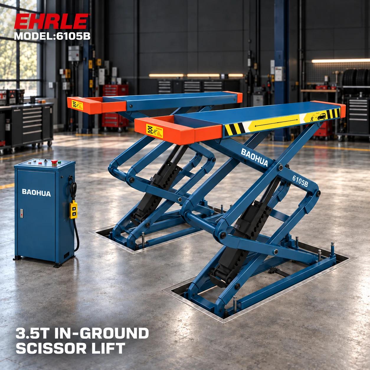
Product scene illustration. Confirm cabinet location, approved service routes and the exact platform-extension configuration on the final drawing.