Scissor Lift Platform Extensions: Match the Arrangement to Vehicle Lifting Points
Review 6105B extension options and 6010B/C base versus extended dimensions. Confirm usable support areas and vehicle lifting points before selecting the package.
Define the support-point problem before selecting extensions
A short-platform scissor lift needs to match the vehicle’s approved lifting points and pad arrangement. An extended platform dimension helps describe the equipment, but does not by itself establish the usable contact area, vehicle wheelbase range or permissible load distribution.
For a mixed fleet, send the supplier the actual vehicle support-point information and ask which documented platform configuration fits. This guide uses EHRLE 6105B and 6010B/C to separate extension choices from assumptions about vehicle length and capacity. It does not authorize where to place pads or how to deploy an extension.
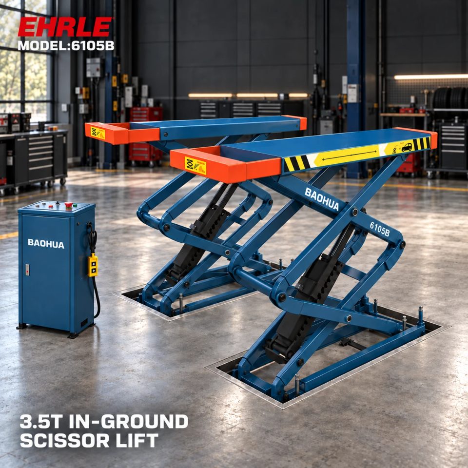
6105B: single-side extension is standard; double-side is an order option
The 6105B record describes a 3,500 kg recessed double-scissor lift with single-side platform extension as standard and double-side extension as optional. The chosen arrangement belongs in the quotation and installation drawing before floor work is finalized.
Request a drawing that identifies which platform ends extend and the permitted configurations. Do not interpret single-side or double-side from a photograph alone. The current specification table does not give verified numerical platform lengths, extension travel or allowable pad locations for either version. Obtain those details rather than copying values from another scissor lift.
6010B/C: distinguish base length from extended length
The 6010B lists 1,420 mm platform length and 2,028 mm with extensions, with 460 mm width per platform. The 6010C lists 1,570 mm and 2,175 mm respectively, with 530 mm width per platform. These figures distinguish the documented base and extended arrangements.
They are not separate published minimum and maximum vehicle wheelbases. Request the drawing and instructions that identify the usable support areas in the selected arrangement, together with the supplied pads. Do not assume every point along the overall extended outline is an approved load-contact position.
Vehicle wheelbase and lifting-point spacing answer different questions
Wheelbase describes the vehicle’s axle arrangement. A wheel-free short-platform lift instead needs a match to the manufacturer-approved support points and their surrounding clearance. A vehicle’s wheelbase or overall body length alone does not locate those points.
Provide the applicable lifting-point diagram and the dimensions needed for the supplier to assess the pad positions. Include relevant underbody obstructions and the intended service task. If support-point information is missing, keep the vehicle assessment pending; choosing the longest extension option does not fill that evidence gap.
An extension changes geometry, not the published lift rating
The current records rate 6010B at 3,000 kg, 6010C at 4,000 kg and 6105B at 3,500 kg for their complete lifts. They do not establish extra capacity gained by extending the platforms or a separate full-lift rating available on each platform.
Ask the supplier to confirm the permitted load distribution and conditions for each extension arrangement. The current records supply no numerical extension-specific contact-load limit or universal edge allowance. Do not create one from the platform dimensions, or assume a main capacity rating resolves every local support condition.
Keep the extension option coordinated with the installation
For 6105B, settle the selected extension package before approving the final recessed layout. The corresponding drawings need to establish the platform envelope and applicable installation requirements. A surface-mounted or portable model’s drawing is not a substitute for that recessed configuration.
For 6010B/C, request the actual supplied extension and pad scope with the layout and operating documents. Neither product record establishes interchangeable extensions across these models. If a proposed vehicle cannot be matched to an approved arrangement, request an appropriate configuration review rather than a workshop-made extension or an undocumented accessory substitution.
A practical order schedule for platforms and extensions
Include:
1. Exact model and single-side/double-side option where applicable.
2. Dimensioned base and extended arrangements, with each measuring point identified.
3. Supplied pad/adapter package and permitted support areas.
4. Vehicle lifting-point information, relevant weight and load distribution.
5. The supplier’s compatibility assessment and any unresolved vehicle conditions.
6. The matching installation drawing and extension operating/inspection instructions.
Have the supplier explain the permitted arrangement through the exact documents and training. At handover, compare the delivered platform and extension package with the approved order. Installation and any electrical or hydraulic work must follow those model-specific documents and qualified site assessment.
Contact EHRLE with your vehicle list and support-point diagrams to review 6105B or 6010B/C. The purchase decision should identify an approved support arrangement rather than rely on a maximum extended length alone.
FAQ: Does the 6010C 2,175 mm extended length specify its maximum wheelbase?
No such wheelbase limit is established by the record. It is a platform dimension. Assess the vehicle’s approved lifting points and permitted pad arrangement using the selected model drawing.
FAQ: Is double-side extension included on every 6105B?
No. Single-side extension is the listed standard; double-side extension is an option. Name the version in the quotation and coordinate it with the final installation drawing.
FAQ: Can extending the platforms increase rated capacity?
The current records establish no such increase. Keep the complete-lift rating and the manufacturer’s permitted support/load-distribution conditions in the assessment.
Sources and image notes
This guide uses published, enabled and verified EHRLE 6105B and 6010B/6010C records checked on 23 October 2026. Related pages are linked below. It focuses on extension geometry, support-area evidence and configuration identity, beyond earlier low-rise/full-rise task selection and recessed construction-document guides.
The cover and gallery are product scene illustrations, not scaled extension drawings or proof of approved pad locations. The 6010B/C scene explicitly shows a 3T configuration; it does not establish 4T dimensions, loading performance or inclusion of every accessory.
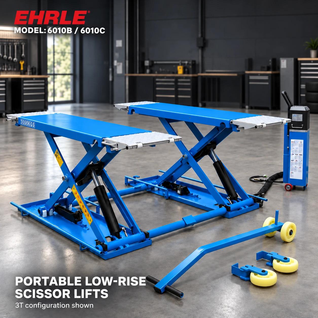
Product scene illustration, 3T configuration shown. Use the selected model drawing to establish the actual extension arrangement and permitted support areas.