Two-Post Lift Bay Access: Drive-Through Width, Doors and Working Space
Use EC500 dimensions to separate equipment width, column spacing, drive-through access and vehicle-door clearance when planning a two-post service bay.
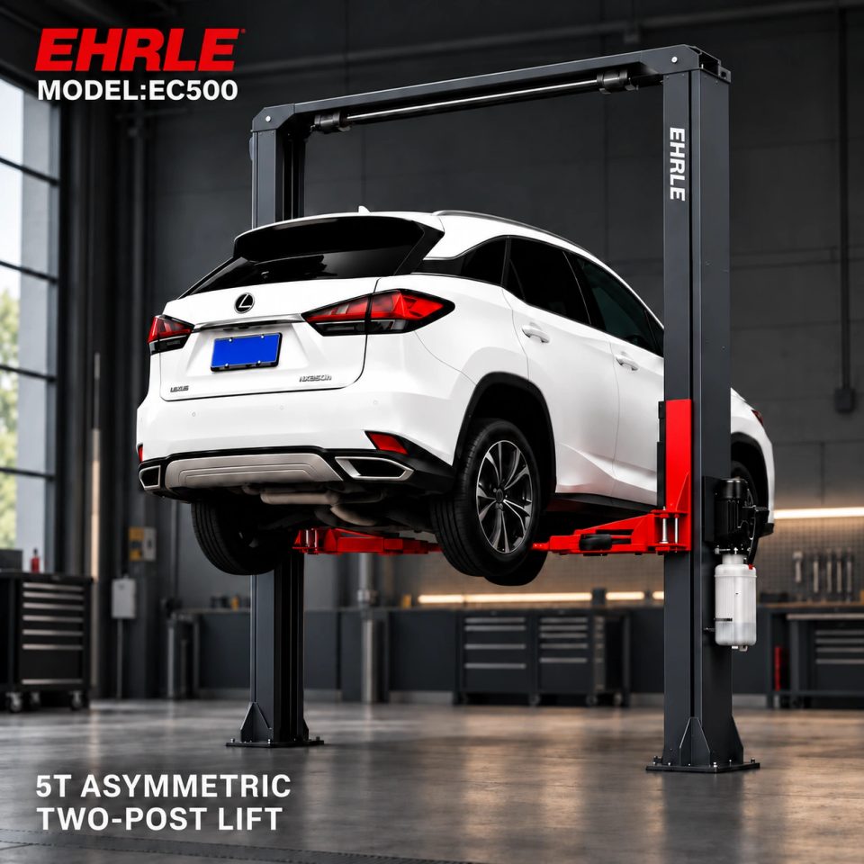
A lift can fit the floor plan while vehicle access still needs review
The EHRLE EC500 has a listed overall width of 3,500 mm. That equipment dimension does not establish the complete working width of a service bay. Vehicle approach, door movement and access around the posts must also be reviewed for the actual vehicles and workshop layout.
Before choosing a position for the lift, ask what people and equipment need to do around a correctly supported vehicle. Provide those requirements with the vehicle details and measured plan, so the supplier can assess the installation and vehicle positioning together. Do not treat spare space beside a drawn equipment outline as confirmed door clearance.
Label the four EC500 width measurements correctly
The EC500 record lists 3,500 mm overall width, 3,260 mm front-view upper width, 2,840 mm clear distance between columns and 2,500 mm drive-through width. These values refer to different measuring positions. They should not be used interchangeably when checking the approach or the space around the vehicle.
Request a drawing that labels each measurement and shows the relevant structure. For an initial approach discussion, identify the listed drive-through opening separately from column spacing. The drawing and the actual vehicle dimensions must determine the final assessment; no single width proves complete vehicle compatibility.
The 45-degree asymmetric layout does not define a universal door opening
The EC500 is listed with 45-degree asymmetric columns. Its product information identifies vehicle entry, exit and door access as planning considerations, while stating that available clearance still depends on vehicle width, door geometry and vehicle position.
Ask the supplier to assess the intended vehicles in their permitted support positions. The current record does not provide an approved door-opening angle or a universal minimum working gap. Do not invent one, or assume the column angle guarantees the same door access for every sedan, SUV or pickup.
Keep the approved support arrangement in the access assessment
The EC500 is rated at 5,000 kg and lists 90 mm minimum height. Neither figure settles arm reach, pad access, approved lifting-point geometry or load distribution for an individual vehicle. These conditions must be checked alongside the desired access.
A plan intended to improve door clearance still needs a vehicle position that meets the model instructions and the vehicle’s approved support requirements. Request the actual arm-range and adapter information before approving the layout. This guide does not prescribe a new vehicle-positioning method or permission to move a support point for convenience.
Include floor-level movements in a mixed-workshop comparison
For the separate EF450 floor-plate lift, the current record lists 3,530 mm overall width, 3,000 mm clear column spacing and 2,730 mm drive-through width. Its floor-level connecting plate is another feature that the vehicle approach and movement of workshop equipment need to account for.
This comparison identifies questions for the bay plan; it does not declare that one model always gives better access. The EF450 minimum pad height of 110 mm is a pad-access dimension, not the connecting-plate height. Obtain the actual plate and layout information rather than using that number to assess floor-level passage.
Review overhead space as a separate part of the bay
The EC500 lists 3,720 mm overall height and 1,800 mm maximum lifting height. Overall structure height is not a minimum ceiling-height recommendation. The raised vehicle, overhead services and permitted operating arrangement must be considered on the model-specific layout.
Supply the actual ceiling height and obstruction positions along with the floor plan. Successful horizontal access does not establish vertical clearance, just as a high ceiling does not resolve door access. Ask for confirmation of both using the same selected vehicle and equipment configuration.
A useful site brief for vehicle and operator access
Send EHRLE:
1. Representative vehicle models, body dimensions and relevant door geometry.
2. Vehicle weights, approved lifting points and any pad-access concerns.
3. Measured entrances, walls, obstructions and intended approach.
4. The access needed beside the supported vehicle and the equipment used around it.
5. Ceiling height and overhead services.
6. The proposed model, arm/adapter arrangement and electrical supply.
Request a labelled installation layout and a vehicle-specific compatibility review. Have the qualified installer assess the site using the applicable foundation, anchoring and operating documents. The current product records do not supply a universal bay-width allowance or a door-clearance formula for this article to prescribe.
FAQ: Can I use clear column spacing as drive-through width?
Use the separately listed measurements and their drawing locations. For EC500 the values are 2,840 mm and 2,500 mm respectively; for EF450 they are 3,000 mm and 2,730 mm. The measurements describe different openings.
FAQ: Does a 45-degree column arrangement guarantee that every door opens fully?
No universal door-opening claim is established by the current record. Confirm actual vehicle width, door geometry and the permitted support position on the proposed layout.
FAQ: Is overall equipment width the required bay width?
It describes the equipment envelope. Approach, doors and working access require additional vehicle- and site-specific assessment using the exact drawing.
Sources and image notes
This guide uses current EHRLE EC500 and EF450 product records checked on 15 October 2026. Related product pages are linked below. The cover is a product scene illustration, not a scaled clearance drawing or evidence of an approved installation for the pictured vehicle. Confirm final support positions, arm configuration and site requirements using the applicable documents.